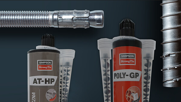
Kotwa mechaniczna
Kotwy BOAX-II charakteryzuje się szybkością montażu i wysoką nośnością przy niewielkich odległościach pomiędzy kotwiami i niewielkich odległościach krawędziowych.
Szczegóły produktu
Właściwości
Materiał
- Stal nierdzewna A4
Zalety
- Szybkiego montażu w zarysowanym i niezarysowanym betonie (opcj1).
- Zoptymalizowany klips rozporowy gwarantuje równomierny rozkład naprężeń umożliwiąjcy stosowanie przy dużych obciążeniach dopuszczalnych oraz małe odstępy osiowe do krawędzi w przypadku niewielkich elementów budowlanych.
- Zwiększona wytrzymałość na rozciąganie i ścinanie.
Zastosowanie
Obszar zastosowań
Stosowane są głównie do mocowania w podłożach gładkich i twardych tj. beton, żelbet itp. Kotwa przeznaczona jest do mocowania w zakresie średnich obciążeń elementów konstrukcji budowlanych:
- Elewacji
- Barier
- Poręczy
- Konstrukcji metalowych
- Profili metalowych
- Podstaw do maszyn
- Konsoli, konstrukcji drewnianych
- Belek
- Płatwi
- Wieszaków itp.
Dane techniczne
Wymiary złącza
| Referencje | Kod produktu | Klasa seismiczna C1/C2 | Tun / DB nr. | * | Rozmiar gwintu [mm] | Długość [L] [mm] | Maksymalna grubośc elementu mocowanego [tfix] [mm] | Długosc gwintu [F] [mm] | Średnica otworu w elemncie mocowanym [df] [mm] | Głębokośc wiercenia [hef] [mm] | Średnica wiercenia X głębokość wiercenia [d0 x h1] [mm] | Ilość w opakowaniu |
|---|---|---|---|---|---|---|---|---|---|---|---|---|
| BOAX-II M20-170/20 A4* | BOAX2020110020A4 | - | - | - | 20 | 170 | 20 | 55 | 22 | 110 | 20x130 | 5 |
| BOAX M20-220/70 A4* | BOAX2020110070A4 | - | - | - | 20 | 220 | 70 | 55 | 22 | 110 | 20x130 | 5 |
* Nie objęte aprobatą
Nośności
| Referencje | Beton zarysowany | Moment zginający [Mrds] [Nm] | |||||||||
|---|---|---|---|---|---|---|---|---|---|---|---|
| Rozciąganie - Nrec [Nrec] [kN] | Ścinanie - Vrec(1-3) [Vrec] [kN] | Rozciąganie [NRd] [kN] | Ścinanie [VRd] [kN] | ||||||||
| C20/25 | C30/37 | C40/50 | C50/60 | C20/25 | C30/37 | C40/50 | C50/60 | C20/25 | C20/25 | ||
| BOAX-II M20-170/20 A4* | - | - | - | - | - | - | - | - | - | - | 185.4 |
| BOAX M20-220/70 A4* | - | - | - | - | - | - | - | - | - | - | 185.4 |
* Nie objęte aprobatą
Obciążenia rekomendowane
| Referencje | Beton niezarysowany | |||||||||
|---|---|---|---|---|---|---|---|---|---|---|
| Rozciąganie - Nrec(1-2) [Rds,N] [kN] | Ścinanie - Vrec(1-3) [Rds,V] [kN] | Rozciąganie [NRd] [kN] | Ścinanie [VRd] [kN] | |||||||
| C20/25 | C30/37 | C40/50 | C50/60 | C20/25 | C30/37 | C40/50 | C50/60 | |||
| BOAX-II M20-170/20 A4* | 13.9 | 13.9 | 13.9 | 13.9 | 13.9 | 13.9 | 13.9 | 13.9 | - | - |
| BOAX M20-220/70 A4* | 13.9 | 13.9 | 13.9 | 13.9 | 13.9 | 13.9 | 13.9 | 13.9 | - | - |
* Nie zawarte w ETA-08/0276
1) Zalecane obciążenia zostały obliczone na podstawie nośności charakterystycznych podanych w ETA z częściowymi współczynnikami bezpieczeństwa podanymi w ETAG001 i częściowym współczynniku bezpieczeństwa dla obciążeń: f = 1,4.
2) Zalecane obciążenia osiowe obowiązują dla betonu zbrojonego i żelbetu z odstępem między prętami s ≥ 15 cm (dowolna średnica) lub z odstępem zbrojenia s ≥ 10 cm, jeśli średnica pręta zbrojeniowego wynosi 10 mm lub mniej.
3) Dane dotyczące ścinania dotyczą pojedynczej kotwy bez wpływu krawędzi betonu. Dla zakotwień bliskich krawędzi (c ≤ max [10 hef; 60d]) należy sprawdzić uszkodzenie krawędzi betonu zgodnie z ETAG 001, załącznik C, metoda projektowania A.
4) Beton jest uważany za niezarysowany, gdy naprężenie rozciągające w betonie wynosi \ sigmaL + \ sigmaR ≤ 0. W przypadku braku szczegółowej danych można przyjąć, że \ sigmaR = 3 N / mm² (\ sigmaL jest równe wytrzymałości na rozciąganie
naprężenia w betonie wywołane przez obciążenia zewnętrzne, w tym obciążenia od kotew).
6) Zalecany moment gnący obowiązuje tylko dla prętów gwintowanych.
Design capacities - single anchor - no edge distances - Non-cracked concrete
| Referencje | Design capacity - Non-cracked concrete | ||||||||
|---|---|---|---|---|---|---|---|---|---|
| Tension - NRd [kN] | Shear - VRd [kN] | Bending moment - MRd [Nm] | |||||||
| C20/25 | C30/37 | C40/50 | C50/60 | C20/25 | C30/37 | C40/50 | C50/60 | ||
| BOAX-II M20-170/20 A4* | 19.5 | 19.5 | 19.5 | 19.5 | 19.5 | 19.5 | 19.5 | 19.5 | 259.6 |
| BOAX M20-220/70 A4* | 19.5 | 19.5 | 19.5 | 19.5 | 19.5 | 19.5 | 19.5 | 19.5 | 259.6 |
1. The design loads loads have been calculated using the partial safety factors for resistances stated in ETA-approval(s). The loading figures are valid for unreinforced concrete and reinforced concrete with a rebar spacing s ≥ 15 cm (any diameter) or with a rebar spacing s ≥ 10 cm, if the rebar diameter is 10mm or smaller.
2. The figures for shear are based on a single anchor without influence of concrete edges. For anchorages close to edges (c ≤ max [10 hef; 60d]) the concrete edge failure shall be checked per ETAG 001, Annex C, design method A.
3. Concrete is considered non-cracked when the tensile stress within the concrete is\sigmaL +\sigmaR ≤ 0. In the absence of detailed verification\sigmaR = 3 N/mm² can be assumed (\sigmaL equals the tensile stress within the concrete induced by external loads, anchors loads included).
*Not covered by ETA-08/0276
Design capacities - single anchor - no edge distances - Cracked concrete
| Referencje | Design capacity - Non-cracked concrete | ||||||||
|---|---|---|---|---|---|---|---|---|---|
| Tension - NRd [kN] | Shear - VRd [kN] | Bending moment - MRd [Nm] | |||||||
| C20/25 | C30/37 | C40/50 | C50/60 | C20/25 | C30/37 | C40/50 | C50/60 | ||
| BOAX-II M20-170/20 A4* | - | - | - | - | - | - | - | - | - |
| BOAX M20-220/70 A4* | - | - | - | - | - | - | - | - | - |
1. The design loads loads have been calculated using the partial safety factors for resistances stated in ETA-approval(s). The loading figures are valid for unreinforced concrete and reinforced concrete with a rebar spacing s ≥ 15 cm (any diameter) or with a rebar spacing s ≥ 10 cm, if the rebar diameter is 10mm or smaller.
2. The figures for shear are based on a single anchor without influence of concrete edges. For anchorages close to edges (c ≤ max [10 hef; 60d]) the concrete edge failure shall be checked per ETAG 001, Annex C, design method A.
3. Concrete is considered non-cracked when the tensile stress within the concrete is\sigmaL +\sigmaR ≤ 0. In the absence of detailed verification\sigmaR = 3 N/mm² can be assumed (\sigmaL equals the tensile stress within the concrete induced by external loads, anchors loads included).
*Not covered by ETA-08/0276
Recommended capacities - single anchor - no edge distances - Non-cracked concrete
| Referencje | Recommended capacity - Non-cracked concrete | ||||||||
|---|---|---|---|---|---|---|---|---|---|
| Tension - Nrec [kN] | Shear - Vrec [kN] | Bending moment - Mrec [Nm] | |||||||
| C20/25 | C30/37 | C40/50 | C50/60 | C20/25 | C30/37 | C40/50 | C50/60 | ||
| BOAX-II M20-170/20 A4* | 13.9 | 13.9 | 13.9 | 13.9 | 13.9 | 13.9 | 13.9 | 13.9 | 185.4 |
| BOAX M20-220/70 A4* | 13.9 | 13.9 | 13.9 | 13.9 | 13.9 | 13.9 | 13.9 | 13.9 | 185.4 |
1. The recommended loads have been calculated using the partial safety factors for resistances stated in ETA-approval(s) and with a partial safety factor for actions of γF=1.4. The loading figures
are valid for unreinforced concrete and reinforced concrete with a rebar spacing s ≥ 15 cm (any diameter) or with a rebar spacing s ≥ 10 cm, if the rebar diameter is 10 mm or smaller.
2. The figures for shear are based on a single anchor without influence of concrete edges. For anchorages close to edges (c ≤ max [10 hef; 60d]) the concrete edge failure shall be checked per
ETAG 001, Annex C, design method A.
3. Concrete is considered non-cracked when the tensile stress within the concrete is\sigmaL +\sigmaR ≤ 0. In the absence of detailed verification\sigmaR = 3 N/mm² can be assumed (\sigmaL equals the tensile stress within the concrete induced by external loads, anchors loads included).
Recommended capacities - single anchor - no edge distances - Cracked concrete
| Referencje | Recommended capacity - Cracked concrete | ||||||||
|---|---|---|---|---|---|---|---|---|---|
| Tension - Nrec [kN] | Shear - Vrec [kN] | Bending moment - Mrec [Nm] | |||||||
| C20/25 | C30/37 | C40/50 | C50/60 | C20/25 | C30/37 | C40/50 | C50/60 | ||
| BOAX-II M20-170/20 A4* | - | - | - | - | - | - | - | - | - |
| BOAX M20-220/70 A4* | - | - | - | - | - | - | - | - | - |
1. The recommended loads have been calculated using the partial safety factors for resistances stated in ETA-approval(s) and with a partial safety factor for actions of γF=1.4. The loading figures
are valid for unreinforced concrete and reinforced concrete with a rebar spacing s ≥ 15 cm (any diameter) or with a rebar spacing s ≥ 10 cm, if the rebar diameter is 10 mm or smaller.
2. The figures for shear are based on a single anchor without influence of concrete edges. For anchorages close to edges (c ≤ max [10 hef; 60d]) the concrete edge failure shall be checked per
ETAG 001, Annex C, design method A.
3. Concrete is considered non-cracked when the tensile stress within the concrete is\sigmaL +\sigmaR ≤ 0. In the absence of detailed verification\sigmaR = 3 N/mm² can be assumed (\sigmaL equals the tensile stress within the concrete induced by external loads, anchors loads included)
Instalacja
Montaż
Montaż
- Wywiercić otwór o odpowiedniej średnicy i głębokości. Patrz instrukcja dołączona do produktu.
- Usunąć zwierciny z otworu za pomocą ręcznej pompki.
- Włożyć kotwę do otworu lub przelotowo przez mocowany element i dobić ją młotkiem na odpowiednią głębokość.
- Używając klucza dynamometrycznego dokręcić kotwę do wymaganego momentu. Patrz instrukcja dołączona do produktu lub tabela parametry montażowe
Dane montażowe
| Referencje | Średnica wiercenia [d0] [mm] | Głębokość wiercenia [h1] [mm] | Średnica otworu w elemncie mocowanym [df] [mm] | Rozmiar klucza [SW] | Moment montażowy [Tinst] [Nm] | Efektywna głębokość kotwienia [hef] [mm] | Rozstaw charakterystyczny - Scr,N [scr,N] [mm] | Rozstaw minimalny [smin] [mm] | Charakterystyczna odległośc od krawędzi - Ccr,N [ccr,N] [mm] | Minimalna odległośc od krawędzi [cmin] [mm] | Minimalna grubośc podłoża [hmin] [mm] |
|---|---|---|---|---|---|---|---|---|---|---|---|
| BOAX-II M20-170/20 A4* | 20 | 130 | 22 | 30 | 240 | 110 | 400 | 400 | 300 | 300 | 180 |
| BOAX M20-220/70 A4* | 20 | 130 | 22 | 30 | 240 | 110 | 400 | 400 | 300 | 300 | 180 |


